
10G CWDM SFP+/XFP
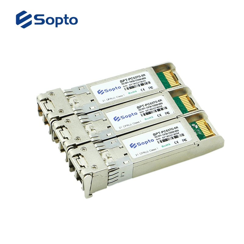
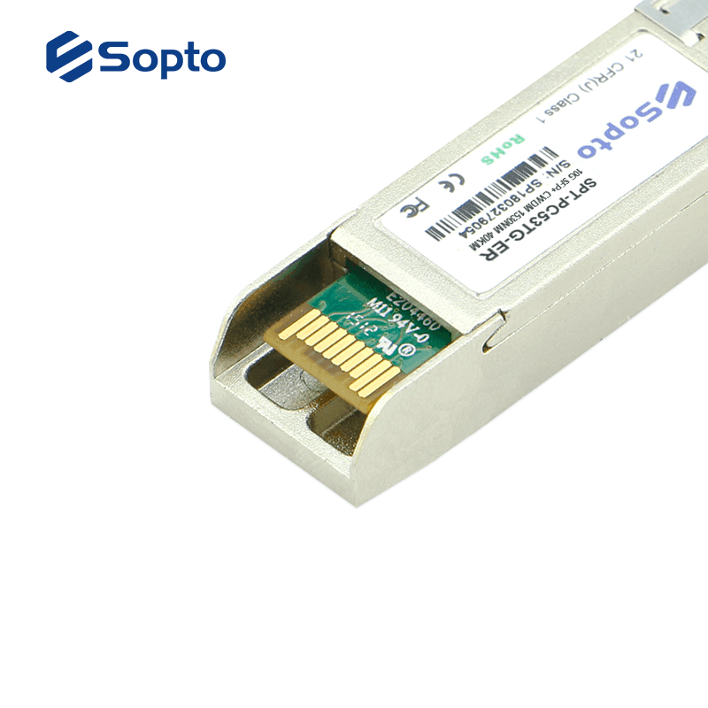
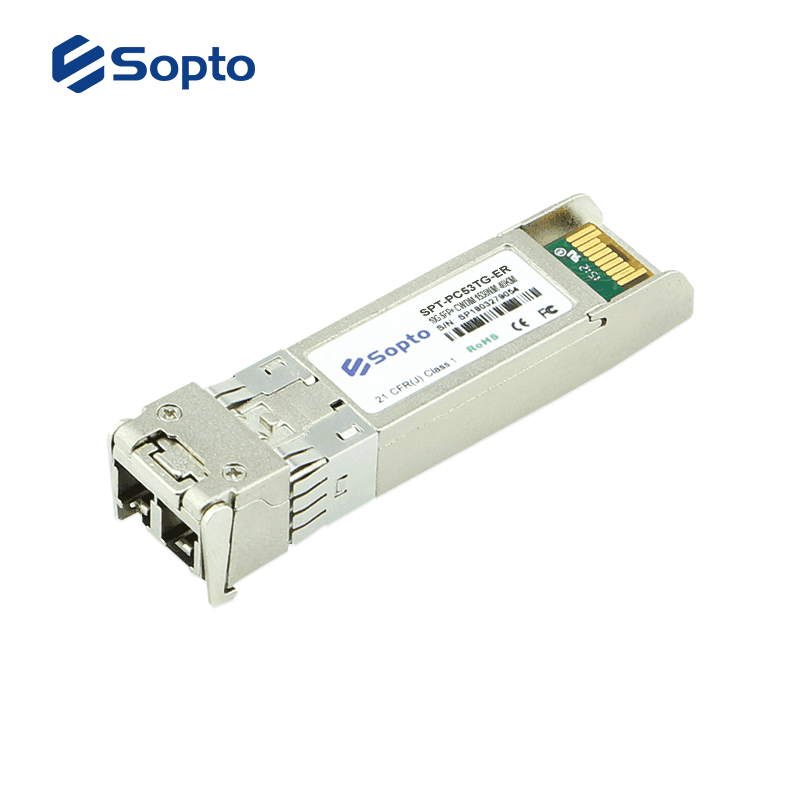
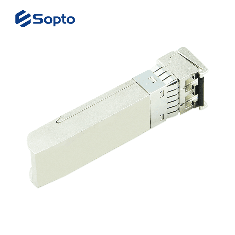
10G CWDM SFP+/XFP transceiver modules are small form factor pluggable module for serial optical data communications. It is designed for single mode fiber and operates at a nominal wavelength of CWDM wavelength. There are 18 center wavelengths available from 1270 nm to 1610 nm, with each step 20 nm. A guaranteed minimum optical link budget of 14 dB is offered. Sopto supplies OEM service and Third-Party(Cisco, Juniper, HP, Dell etc.) compatible fiber optic transceivers.
Confirma disponibilidad, instalación y entrega con un asesor.
Descripción
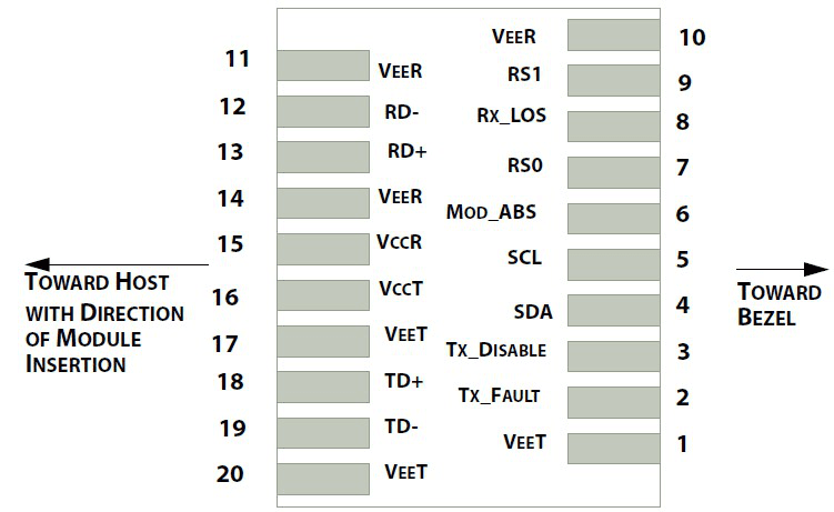
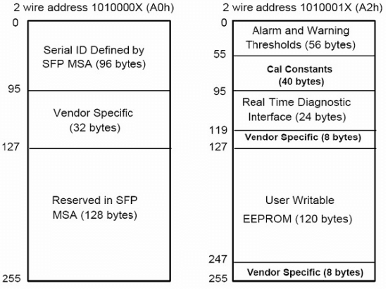
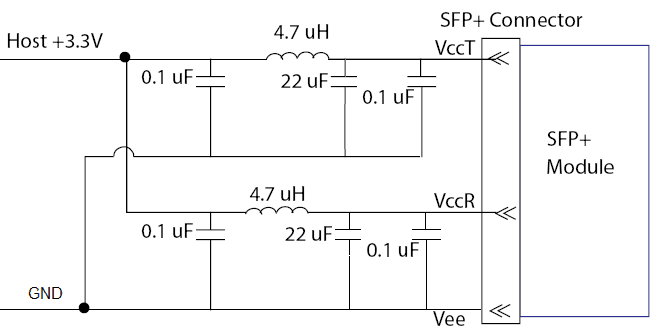
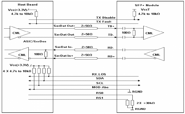
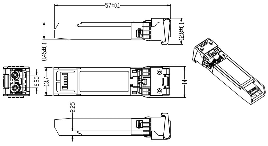
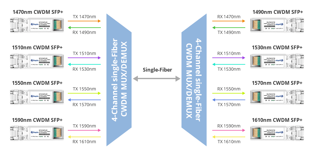
10G CWDM SFP+/XFP transceiver modules are small form factor pluggable module for serial optical data communications. It is designed for single mode fiber and operates at a nominal wavelength of CWDM wavelength. There are 18 center wavelengths available from 1270 nm to 1610 nm, with each step 20 nm. A guaranteed minimum optical link budget of 14 dB is offered. Sopto supplies OEM service and Third-Party(Cisco, Juniper, HP, Dell etc.) compatible fiber optic transceivers. Feature Product Features ● Single +3.3 V Power Supply ● Built-in digital diagnostic functions ● 2G/4G/8G/10G Fibre Channel compliance ● Transmission distance up to 80km over SMF ● Power Budget up to 10dB, 14dB, 16dB, 23 dB ● Supports Multi Protocol 8.5Gb/s, 9.95Gb/s to 11.3Gb/s bit rates ● Class 1 Laser International Safety Standard IEC-60825 Compliant ● Uncooled 18-λ CWDM DFB/cooled EML LD: from 1270 nm to 1610 nm ● Can be used with single fiber CWDM system or dual fiber CWDM system ● Operating Case Temperature: Standard: 0~70°C; Extended: -20~85°C; Industrial: -40~85°C Compliant ● RoHS-6 ● IEEE 802.3ae 10GBASE ● SFF-8431, SFF-8432, SFF-8472 Sopto fiber optic transceiver took the first lead to pass the ISO9001 quality system, the requirements of European CE, RoHs Pin Assignment Diagram of Host Board Connector Block Pin Numbers and Name. Pin Function Definitions P IN Name Function Notes 1 VeeT Module transmitter ground Note 1 2 Tx Fault Module transmitter fault Note 2 3 Tx Disable Transmitter Disable; Turns off transmitter laser output Note 3 4 SDL 2 wire serial interface data input/output (SDA) 5 SCL 2 wire serial interface clock input (SCL) 6 MOD-ABS Module Absent, connect to VeeR or VeeT in the module Note 2 7 RS0 Rate select0,optionally control SFP+ receiver. When high, input data rate>4.5Gb/ s;when low, input data rate <=4.5Gb/s 8 LOS Receiver Loss of Signal Indication Note4 9 RS1 Rate select0,optionally control SFP+ transmitter. When high, input data rate >4.5Gb/s;when low, input data rate <=4.5Gb/s 10 VeeR Module receiver ground Note 1 11 VeeR Module receiver ground Note 1 12 RD- Receiver inverted data out put 13 RD+ Receiver non-inverted data out put 14 VeeR Module receiver ground Note 1 15 VccR Module receiver 3.3V supply 16 VccT Module transmitter 3.3V supply 17 VeeT Module transmitter ground Note 1 18 TD+ Transmitter inverted data out put 19 TD- Transmitter non-inverted data out put 20 VeeT Module transmitter ground Note1 Note 1. The module ground pins shall be isolated from the module case. 2.This pin is an open collector/drain output pin and shall be pulled up with 4.7K-10Kohms to Host_Vcc on the host board. 3.This pin shall be pulled up with 4.7K-10Kohms to VccT in the module. 4.This pin is an open collector/drain output pin and shall be pulled up with 4.7K-10Kohms to Host_Vcc on the host board. SFP Module EEPROM Information and Management The SFP modules implement the 2-wire serial communication protocol as defined in the SFP -8472. The serial ID information of the SFP modules and Digital Diagnostic Monitor parameters can be accessed through the I2C interface at address A0h and A2h. The memory is mapped in Table 1. Detailed ID information(A0h) is listed in Table 2. And the DDM specification at address A2h. For more details of the memory map and byte definitions, please refer to the SFF-8472, “Digital Diagnostic Monitoring Interface for Optical Transceivers”. The DDM parameters have been internally calibrated. Table 1. Digital Diagnostic Memory Map (Specific Data Field Descriptions) Table 2. EEPROM Serial ID Memory Contents ( A0h ) Data Address Length (Byte) Name of Length Description and Contents Base ID Fields 0 1 Identifier Type of Serial transceiver (03h=SFP) 1 1 Reserved Extended identifier of type serial transceiver (04h) 2 1 Connector Code of optical connector type (07=LC) 3-10 8 Transceiver 11 1 Encoding NRZ(03h) 12 1 BR,Nominal Nominal baud rate, unit of 100Mbps 13-14 2 Reserved (0000h) 15 1 Length(9um) Link length supported for 9/125um fiber, units of 100m 16 1 Length(50um) Link length supported for 50/125um fiber, units of 10m 17 1 Length(62.5um) Link length supported for 62.5/125um fiber, units of 10m 18 1 Length(Copper) Link length supported for copper, units of meters 19 1 Reserved 20-35 16 Vendor Name SFP vendor name: SOPTO 36 1 Reserved 37-39 3 Vendor OUI SFP transceiver vendor OUI ID 40-55 16 Vendor PN Part Number: (ASCII) 56-59 4 Vendor rev Revision level for part number 60-62 3 Reserved 63 1 CCID Least significant byte of sum of data in address 0-62 Extended ID Fields 64-65 2 Option Indicates which optical SFP signals are implemented (001Ah = LOS, TX_FAULT, TX_DISABLE all supported) 66 1 BR, max Upper bit rate margin, units of % 67 1 BR, min Lower bit rate margin, units of % 68-83 16 Vendor SN Serial number (ASCII) 84-91 8 Date code SOPTO’s Manufacturing date code 92-94 3 Reserved 95 1 CCEX Check code for the extended ID Fields (addresses 64 to 94) Vendor Specific ID Fields 96-127 32 Readable SOPTO specific date, read only 128-255 128 Reserved Reserved for SFF-8079 Recommended Host Board Power Supply Circuit Recommended High-speed Interface Circuit Mechanical Dimensions All optical transceivers are RoHS compliant and could be 100% compatible with branding equipment, such as Cisco, Extreme, Juniper, HP, H3C, Linksys, Huawei, Alcatel-Lucent, Foundry, Nortel, Force10 etc. If you want to know more about the exact information of the specified transceiver or get price, Please Contact Us>> . Applications ● SONET OC-192 / SDH STM-64 ● OTN ITU-T G.709 ● 10GBASE-SR/LR/ER/ZR Ethernet ● 10X/8X/4X/2X/1X Fibre Channel ● CWDM Networks Related Articles ● What is SFP-10G-LRM Optical Transceiver? ● The difference of SFP 10G SR LR LRM ER and ZR ● What is DDM Function for Fiber Optic Transceiver? ● F iber Optic Transceiver Module's Selection and Use Skills Ordering Information PN Data Rate(Gbps) Distance Fiber Output Power(dBm) Sensitivity(dBm) Interface Temp. DDM CWDM SFP+ SPT-PC(27-61)TG-LR 9.95~11.3 10km SM -4 ~ 0 -14 Duplex LC 0-70 ℃ D SPT-PC(27-33/47-61)TG-LRS 9.95~11.3 20km SM -5 ~ -1 -17 Duplex LC 0-70 ℃ D SPT-PC(21-33/47-61)TG-ER 9.95~11.3 40km SM -1 ~ 3 -17 Duplex LC 0-70 ℃ D SPT-PC(47-61)TG-ZR 9.95~11.3 80km SM 0 ~ 4 -23 Duplex LC 0-70 ℃ D CWDM XFP SPT-XC(27-61)TG-LR 9.95~11.3 10km SM -4 ~ 0 -14 Duplex LC 0-70 ℃ D SPT-XC(27-33/47-61)TG-LRS 9.95~11.3 20km SM -5 ~ -1 -17 Duplex LC 0-70 ℃ D SPT-XC(21-33 / 47-61)TG-ER 9.95~11.3 40km SM -1 ~ 3 -17 Duplex LC 0-70 ℃ D SPT-XC(47-61)TG-ZR 9.95~11.3 80km SM 0 ~ 4 -23 Duplex LC 0-70 ℃ D
Especificaciones técnicas
Consulta las características del producto con uno de nuestros asesores.